
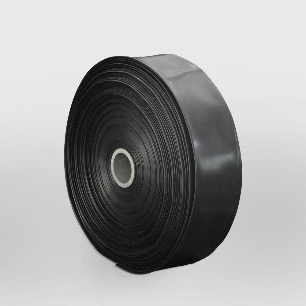
A practical drip irrigation design starts with crop-row length, emitter spacing and emitter flow rate. From these values, you can calculate total water demand, divide the field into workable zones and specify the drip tape, tubes, supply pipes, filters and fittings needed to maintain acceptable pressure and uniformity.
The design should also be checked against actual supplier specifications. Nominal diameter, wall thickness, roll length, operating pressure, emitter tolerance and fitting compatibility can all change the system’s real performance.
Define Crop Rows, Emitter Spacing and Irrigated Area
Begin with the field layout rather than the product catalogue. Record the number of crop rows, row length, distance between rows, planting pattern and the area that must receive water. A system for one crop row per bed is designed differently from a system with two laterals or closely spaced emitters for high-density planting.
Use these basic values:
- Number of rows: total laterals or drip lines required.
- Row length: distance from the inlet connection to the end of each lateral.
- Emitter spacing: distance between individual outlets along the lateral.
- Emitter flow rate: discharge from one emitter at its stated test pressure.
- Irrigated area: planted area, bed area or total field area served by the system.
The approximate number of emitters on one row is:
Row length ÷ emitter spacing
Round the result according to the actual product layout. If a row is 100 m long and emitters are spaced every 0.30 m, the theoretical count is about 333 emitters. The first and last emitter positions may alter the exact count, so confirm the supplier’s emitter placement and the usable length of the roll.
Total lateral length is calculated as:
Number of rows × row length
For example, 40 rows at 100 m each require approximately 4,000 m of lateral material before allowing for headers, connections, damaged ends or installation waste.
Emitter spacing should match the soil, crop and root-zone pattern. Common commercial spacings may range from approximately 10 to 60 cm, but the correct choice depends on soil movement of water, crop spacing, required wetted width and the intended irrigation frequency. Sandy soils generally require closer application points or more frequent irrigation because water moves laterally less than it does in heavier soils. Clay soils may need slower application to reduce runoff and ponding.
Do not select spacing solely because it gives a lower price per roll. A spacing that leaves dry strips between emitters can reduce crop uniformity even when total water volume appears sufficient.
Calculate Emitter Flow Rate and Total Zone Demand
Emitter discharge is normally stated in litres per hour at a specified pressure. Typical commercial values may include approximately 0.6, 1.0, 1.6, 2.0 or 3.0 L/h, although available choices vary by drip tape, drip line and tube construction. The stated value is not a fixed result at every pressure. Confirm the test pressure, discharge tolerance and whether the emitter is pressure-compensating.
Calculate one row’s demand as:
Number of emitters per row × emitter flow rate
Then calculate the total demand of a zone:
Number of rows in the zone × emitters per row × emitter flow rate
For a simple example, a zone contains 20 rows. Each row is 100 m long with emitters every 0.30 m, giving about 333 emitters per row. At 1.6 L/h per emitter:
- Demand per row: 333 × 1.6 = approximately 533 L/h
- Zone demand: 20 × 533 = approximately 10,660 L/h
- Converted to litres per minute: 10,660 ÷ 60 = approximately 178 L/min
- Converted to cubic metres per hour: approximately 10.7 m³/h
This is the calculated application demand before adding allowances for flushing, leakage, filter cleaning, pressure variation and other outlets. If the water source supplies only 8 m³/h at the required pressure, the zone is too large even if the pump’s maximum flow rating appears higher.
Irrigation duration can be estimated from the desired application volume:
Required water volume ÷ zone flow rate = operating time
For area-based planning, convert the target depth into volume. One millimetre of water over one square metre equals approximately one litre. Therefore, a 10 mm application over 1,000 m² requires about 10,000 litres, subject to irrigation efficiency and field conditions.
The design should distinguish between nominal emitter flow and verified operating flow. Ask the supplier for:
- Emitter flow rate at the stated pressure
- Flow-rate tolerance, if available
- Pressure range for stable operation
- Whether outlets are online or integrated
- Filtration requirement and minimum filtration level
- Recommended maximum lateral length at the planned spacing
For greater detail on selecting the lateral product, compare the construction and use conditions in Drip Tape or Drip Line: Choosing the Right Lateral.
Size Irrigation Zones for Available Water Supply
A zone is a group of laterals operated at the same time through a valve or control point. Zone sizing must be based on the water available at the system inlet during operation, not only on the pump nameplate or water-source capacity at zero pressure.
Use this sequence before confirming material quantities:
- Measure or obtain the available flow at the required operating pressure.
- Subtract the expected demand of other simultaneous users, such as tanks, sprinklers or wash-down outlets.
- Calculate lateral demand from emitter count and emitter flow.
- Add a practical allowance for flushing, minor leakage and measurement variation.
- Divide the available flow by the demand of one row to estimate the maximum number of rows per zone.
- Reduce the result if the zone contains long laterals, uneven elevation or significant header losses.
- Confirm that the pump can maintain the pressure required at the zone inlet.
As a simplified example, if the source can deliver 12 m³/h at the design pressure and each row requires 0.53 m³/h, the theoretical capacity is about 22 rows. A buyer should not automatically specify 22 rows as the working zone. A lower operating count may be appropriate after allowing for pressure losses, flushing flow and source variation.
Elevation is important. Pressure decreases as the lateral rises and increases as it falls. As a general engineering approximation, a 10 m change in water elevation can represent about 1 bar of pressure difference, although the exact result depends on water density and measurement conditions. Sloping fields may need shorter zones, pressure-compensating emitters, separate pressure regulation or a layout that follows the contour.
The header and submain must also carry the zone flow. A common design error is to calculate the laterals correctly but use a supply pipe that is too small. Pipe diameter affects friction loss, available pressure and future expansion. Use the outside diameter, inside diameter, pressure class and actual wall thickness when checking capacity. The PE Pipe Diameter and Pressure Guide provides a useful checklist for comparing these specifications.
Do not confuse maximum pump flow with usable irrigation flow. A pump may produce its stated maximum only at low head, while the filter, valves, elevation and pipe friction require additional pressure. Request a pump curve or operating point when the project depends on a fixed flow and pressure combination.
Match Drip Tape, Tubes, Pipes and Fittings to the Design
Once the hydraulic demand is known, match each component to its role. Drip tape is often a thin-wall, seasonal lateral used for row crops and relatively simple layouts. Drip irrigation tube or line generally has a thicker wall and may be selected for longer service life, repeated installation or more demanding field conditions. PE irrigation pipe is commonly used for mains, submains and headers, depending on the design pressure and connection method.
A buyer should request a written specification sheet rather than relying on product names alone. Check the following items:
| Component | Specifications to confirm | Why it affects the design |
|---|---|---|
| Drip tape | Flat width or nominal diameter, wall thickness, emitter spacing, emitter flow, roll length and operating pressure | Determines row length, lifetime, flow and material quantity |
| Drip tube or line | Outside diameter, inside diameter, wall thickness, emitter type, pressure range and maximum recommended lateral length | Affects friction loss, durability and outlet uniformity |
| PE supply pipe | Nominal diameter, actual wall thickness, pressure class, material grade and coil or straight length | Controls zone delivery and pressure loss |
| Fittings | Connection diameter, insertion depth, sealing method, valve compatibility and material | Prevents leaks and assembly mismatch |
| Filter and regulator | Flow capacity, filtration rating, pressure range and cleaning method | Protects emitters and stabilizes inlet pressure |
| End assemblies | Flush valve, end cap or folding method, compatible size and service access | Allows flushing and maintenance at the end of each lateral |
Wall thickness deserves particular attention. Two products can have the same nominal diameter but different wall thicknesses, roll lengths and pressure ratings. A thinner product may be suitable for seasonal use but unsuitable for repeated installation, rocky soil or mechanical handling. Ask whether the stated thickness is nominal or measured, and request the allowed tolerance.
Roll length must match the planned row length with enough allowance for connection and flushing. A roll described as 100 m may not provide 100 m of practical installed length if the ends are damaged, the last emitter position is outside the required area or the product has a stated length tolerance. Confirm whether roll length is guaranteed, approximate or subject to manufacturing tolerance.
Fittings must match the actual tube or tape dimensions. Confirm the connection style, not just the nominal size. Some fittings are designed for a particular flat tape width, while others require a round tube with a defined outside diameter. Check whether grommets, take-off connectors, clamps, valves and end caps are included or sold separately.
Material selection should also reflect water quality. Suspended solids, algae, iron, salts and organic matter can block outlets or damage system performance. For filtration choices, see Drip Irrigation Filters: Screen, Disc or Media. If supply pipes are part of a larger water-delivery network, compare the intended application with the guidance in How to Choose PE Irrigation Pipe.
Check Pressure Uniformity and End-of-Line Performance
A drip system can have the correct total flow and still irrigate unevenly. Pressure at the inlet, middle and end of the lateral should be considered because friction loss reduces pressure along the line. Longer laterals, smaller internal diameters, higher emitter flow and greater elevation changes increase this risk.
Before ordering, ask the supplier for the recommended maximum lateral length under conditions close to your design:
- Emitter spacing and flow rate
- Inlet pressure
- Lateral diameter and wall thickness
- Terrain slope
- Water temperature, where relevant
- Desired uniformity or pressure-compensation requirement
The design should include a pressure regulator when the supply pressure can exceed the lateral’s operating range. Excess pressure may increase discharge, open weak connections or shorten product life. Insufficient pressure may produce poor discharge at the end of the row and prevent pressure-compensating emitters from functioning correctly.
Plan a flushing arrangement. Each lateral should have an accessible end that can be opened periodically. Flush the mains and submains before connecting delicate laterals, then flush the laterals during commissioning. If the end-of-line flow is much lower than expected or the water contains visible particles, investigate filtration, pipe debris, blocked outlets and pressure loss.
A practical acceptance check is to measure pressure at the zone inlet and at representative lateral ends while the system is operating. Also measure flow from a sample of emitters near the beginning, middle and end of the lateral. The supplier should state the product’s allowable discharge variation or manufacturing coefficient when available. Do not treat a catalogue flow rate as proof of field uniformity.
Temperature, installation method and aging can also affect results. Tape stretched over rough ground, sharply bent around a bed edge or exposed to unsuitable chemicals may fail earlier than a correctly installed product. Ask for storage, chemical compatibility and operating instructions before approving a large order.
Common Design Errors Before Ordering Materials
Many purchasing problems originate in an incomplete design rather than a defective product. Check these points before issuing a purchase order.
- Using area alone to calculate flow: Irrigation demand depends on emitter count and discharge, not only on hectares or square metres.
- Ignoring the actual row length: A zone based on a standard roll length may not fit the field layout or may leave unserved sections.
- Mixing emitter specifications: Combining 1.0 L/h and 1.6 L/h laterals in one zone changes the flow calculation and can create uneven application.
- Sizing the pump without pressure: A flow figure without the corresponding pressure or head is not enough for equipment selection.
- Selecting by nominal diameter only: Check inside diameter, outside diameter, wall thickness and pressure class.
- Forgetting filter losses: A dirty or undersized filter can reduce inlet pressure significantly.
- Using incompatible fittings: Confirm the actual dimensions and connection method for every tape, tube and pipe combination.
- Leaving no flushing allowance: End caps that cannot be opened make routine maintenance difficult.
- Ordering exact quantities with no tolerance: Allow for cutting, damaged ends, connections, spare parts and field changes.
- Failing to define quality documents: Specify dimensional tolerance, flow tolerance, roll-length tolerance, packing method and inspection requirements in the purchase order.
For a wholesale project, send the supplier a simple design schedule containing field dimensions, row count, row length, emitter spacing, emitter flow, zone count, source flow, source pressure, elevation difference, filtration requirement and preferred roll length. Ask the supplier to return a matching bill of materials and clearly identify any assumptions.
The final quotation should separate product specifications from optional accessories. Confirm whether filters, regulators, valves, take-offs, grommets, end flush valves, repair couplers and packing are included. Export buyers should also verify roll labels, batch identification, moisture protection and loading dimensions. The Container Loading Guide for Packaging Materials includes broader principles for checking packed-volume assumptions, which can also help when planning irrigation-product shipments.
CZJ Wholesale Team can review a buyer’s field parameters against the requested drip tape, tube and PE pipe specifications, but the final hydraulic design should be checked against the site’s measured water supply, terrain and crop requirements. The most reliable order is one supported by both calculations and a written product specification.
FAQ
How do I calculate drip irrigation flow rate?
Multiply the number of emitters by the emitter discharge in litres per hour. For a zone, multiply the number of emitters per row by the number of rows and the emitter flow rate. Convert litres per hour to cubic metres per hour by dividing by 1,000.
How many emitters can one irrigation zone operate?
Divide the usable source flow at the required pressure by the calculated flow of one row. Reduce the theoretical result when there are long laterals, elevation changes, filter losses, flushing requirements or uncertain source performance.
What emitter spacing should I choose?
Choose spacing according to crop spacing, soil texture, root-zone width and irrigation frequency. Closer spacing may be needed in coarse soils or where continuous wetting is required. Confirm the choice with local agronomic conditions rather than price or roll length alone.
How do I verify a drip tape supplier’s specifications?
Request emitter flow at a stated pressure, spacing tolerance, wall-thickness tolerance, roll-length tolerance, operating-pressure range and recommended maximum lateral length. Check sample dimensions and test flow from representative sections before approving a large order.
Is thicker drip tape always better?
No. A thicker wall generally supports more handling and repeated use, but it may cost more and require a different fitting or pressure range. Select wall thickness according to installation method, expected service life, field hazards and project budget.